ST205 Group A Homologation Features
![]()
To use the ST205 GT-Four in rallying Toyota had to manufacture 2500 production vehicles to meet FIA requirements. These cars were known as Group A models (or WRC in Japan, Group A Rallye in Australia) and most were manufactured early in 1994, travelling down the production line alongside normal GT-Four models.
The easiest way to spot a Group A is the large extensions which lift the rear wing about 15cm. These were added to provide additional downforce and are very effective, unlike 90% of the wings you see nowadays. This is evident by the 20 kph they are reported to knock off the top speed. Trouble is, the extensions can be bolted to any 94-99 Celica, so not a definite way to identify the car.
Japanese WRC models can be spotted by the small wing at the rear edge of the bonnet. In Japan only the WRC got the wing, all export models had it though.
There are no other differences to the exterior or interior, with the exception of a small "Group A Rallye" badge below the GT-Four badge on the Aussie cars. These badges were removed from the five New Zealand cars (which were Australian models).
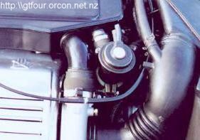
The real fun begins under the bonnet. The intercooler is a different part number, but I'm still not sure why. The two visible changes are the water spray system for the intercooler radiator and the anti-lag system.
Intercooler Water Spray
The water spray system is not operational from the factory, the regulations said the parts had to be there, not necessarily work! There are three small plastic nozzles mounted on the rear of the steel bumper facing the intercooler radiator. On the bottom of the windscreen washer bottle there is a small (500 ml or so) chamber with a pump attached. Given the 10 gauge wiring and general size this is a very powerful pump. Pity it isn't actually wired to anything!
There is also some type of pneumatic pressure regulator fitted to the water bottle. An expensive wee doodah by the look of it, but as this area was smashed apart in the crash I never figured out how it connected. From it one vacuum line went to the cold start injector fuel line fitting (note CS injector isn't actually connected to fuel rail) and the other splices into the vacuum lines on the back of the block. Since I couldn't figure it out, I binned it! There is a also a distribution valve which merges the water pipes from the IC pump and the headlight sprayer pump and selects whether the water goes to the IC sprayers or headlight washers. Again, I couldn't figure this out so I turfed it. Now the IC pump is connected to the IC sprayers, and the headlight pump is connected to the headlight sprayers. A lot simpler? I reckon.
The small cavity on the bottom of the washer tank isn't actually connected to anything. There is a barbed fitting for a hose and a couple of smaller fittings for pipes. I was going to drill through so washer fluid drains down but then I realised that the barbed fitting is intended to take a hose from a larger water tank (inside the car) specifically intended for the IC spray. The smaller fittings may be for breathers of return lines. I intend to get an interior tank with a small feeder pump that can be filled as required.
Wiring is also required. I ran a 10 gauge wire from the fusebox via a relay and fuse. A small wire heads inside so that a small voltage only is required to activate the system. I have yet to decide how this will be done, but refer to the water spray articles at http://www.autospeed.com/A_0527/page1.html.
Anti-Lag
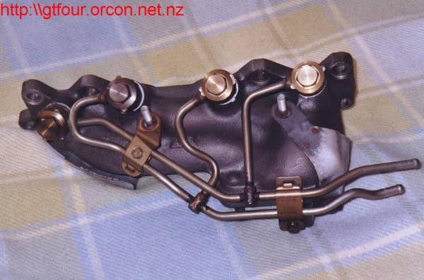
The Group A was the first production car I know of with anti-lag standard, although again not operational. The system uses an ECU signal to switch two VSV's on the back of the block which provide vacuum (via a canister) to the special bypass valve fitted right beside the entrance to the IC. This heavy duty metal valve has a poppet valve which when opened directs some of the air (which usually all goes through the BOV) down four metal tubes into the exhaust manifold. A special manifold has a hole just after each exhaust port. A small heatshield sits between the manifold and the intercooler.
How do you make it work? You don't.
Anti-lag is *very* hard on turbos due to the shockwaves and high temperatures produced. Unless you have a rally team budget, forget it.
Here is some of what you need to do to
activate it. My bypass valve seems to be jammed shut, maybe it has an internal
spacer to stop it opening. The fittings connecting the pipes to the manifold are
also not drilled though. With those aspects fixed the system will mechanically work.
The VSV's are wired to the ECU, however an aftermarket ECU is needed to apply
12V to make them work. I'm guessing that (like most systems) the ECU retards the
timing while continuing fuel injection. The mixture burns in the manifold,
keeping the turbo spinning. This is very harsh on the system, therefore the
pipes are just to supply cool air to keep temperatures down (conjecture!).
![]()
![]() Back to Technical
Notes Page.
Back to Technical
Notes Page.
![]() Back to Home Page.
Back to Home Page.
![]()